Reproduced from https://sites.google.com/site/sbobovyc/writing/reverse-engineering/ply
DISCLAIMER: The information provided here is for educational purposes only.
Introduction
am a huge fan of the Men of War series, and with the release of Assault Squad 2 I decided to have a little fun and do some reverse engineering of the game's 3d file format. For those that are not familiar with this topic, check out my series on Reversing DirectX Games. I hope to go through MoW, MoW:Vietnam, MoW:AS and finally MoW:AS2.
Reconnaissance
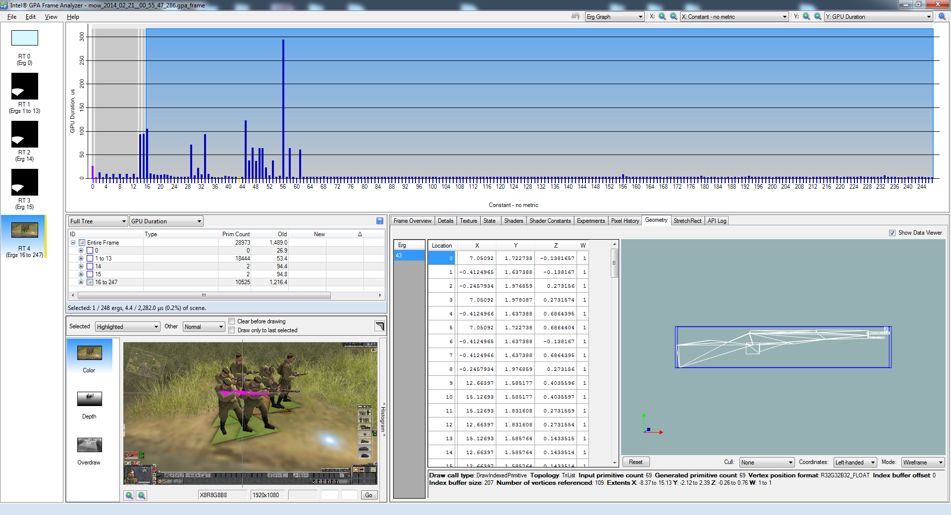
I set the game to the lowest graphics settings and spawned some soviet infantry. Using Intel Frame Analyzer, I captured the geometry of the rifle.
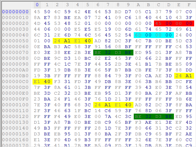
The model of the file can be found by using 7zip to open men of war\resource\entity\e3.pak and grabbing the inventory-weapon\mosin directory. Opening mosin_lod1.ply in a hex editor and searching for vertex count and triangle count came up with hits at the top of the file. Therefore, there is a good chance that this the same model as the one captured by frame analyzer. Here, highlighted in red is the primitive (triangle) count, teal is the vertex count, yellow is the X component of the first vertex, green is X component of second vertex. So, each vertex is 36 bytes long, with first 12 bytes as the XYZ position of the vertex as floats.
Reversing geometry and texture information
Here is a simple Python script to read out the information that is known so far:
import struct

fname = "mosin_lod1.ply"
with open(fname, "rb") as f:
    f.seek(0x2C)
    triangles, = struct.unpack("<I", f.read(4))
    print triangles
    f.seek(0x4A)
    verts, = struct.unpack("<I", f.read(4))
    print verts
    f.seek(0x52)
    for i in range(0, verts):
        vx,vy,vz = struct.unpack("fff24x", f.read(36))
        print vx,vy,vz
To find how the rest of vertex data is arranged, I searched through previous object draw routines for a call to IDirect3DDevice9::SetFVF and IDirect3DDevice9::SetVertexDeclaration. Men of War has many calls to SetFVF which is the older fixed function way to declare a vertex stream format. It also uses Shader model 2.0, which is for the older fixed function pipeline. The draw call that draws the rifle uses SetFVF, so I found the call that preceded the drawing of the rifle geometry I was interested in. The parameter to the call was 338. Looking at d3d9types.h, this corresponds to D3DFVF_XYZ 0x002, D3DFVF_NORMAL 0x010, D3DFVF_DIFFUSE 0x040, D3DFVF_TEX1 0x100. These are all ORed together to produce the parameter to SetFVF:
0x002 | 0x010 | 0x040 | 0x100 = 338I will use this information in reverse engineering the format of mosin_lod1.ply, though I will verify by inspection as if I didn't know this information. Finally, OBJ does not support vertex color, so I will ignore it.
Since this is an indexed mesh, I need to find the list of vertex indices. Looking at the bottom of the file at offset 0xFA6, I see "INDX" followed by 207. 69*3=207, so this must tell us how many elements to read in.
Now, I tested this hypothesis by dumping this data to a Wavefront OBJ file. OBJs indices start at 1 instead of 0, so the script takes care of that.
fname = "mosin_lod1.ply"
positions = []
indeces = []
with open(fname, "rb") as f:
    f.seek(0x2C)
    triangles, = struct.unpack("<I", f.read(4))
    print triangles
    f.seek(0x4A)
    verts, = struct.unpack("<I", f.read(4))
    print "Number of verts:", verts
    f.seek(0x52)
    for i in range(0, verts):
        vx,vy,vz,u1,u2 = struct.unpack("fffff16x", f.read(36))
        print "Vertex %i: " % i,vx,vy,vz
        positions.append((vx,vy,vz))
        #print "u1, u2", u1,u2

    f.seek(0xFAA)
    idx_count, = struct.unpack("<I", f.read(4))
    #print "Indeces:", indeces
    for i in range(0, idx_count/3):
        i0,i1,i2 = struct.unpack("<HHH", f.read(6))
        print "Face %i:" % i,i0,i1,i2
        indeces.append((i0,i1,i2))
    #print(hex(f.tell()))

fname = "mosin_lod1.obj"
with open(fname, "wb") as f:
    for p in positions:
        f.write('{:s} {:f} {:f} {:f}\n'.format("v", *p))
    for idx in indeces:
        new_idx = map(lambda x: x+1, idx)
        f.write('{:s} {:d} {:d} {:d}\n'.format("f", *new_idx))
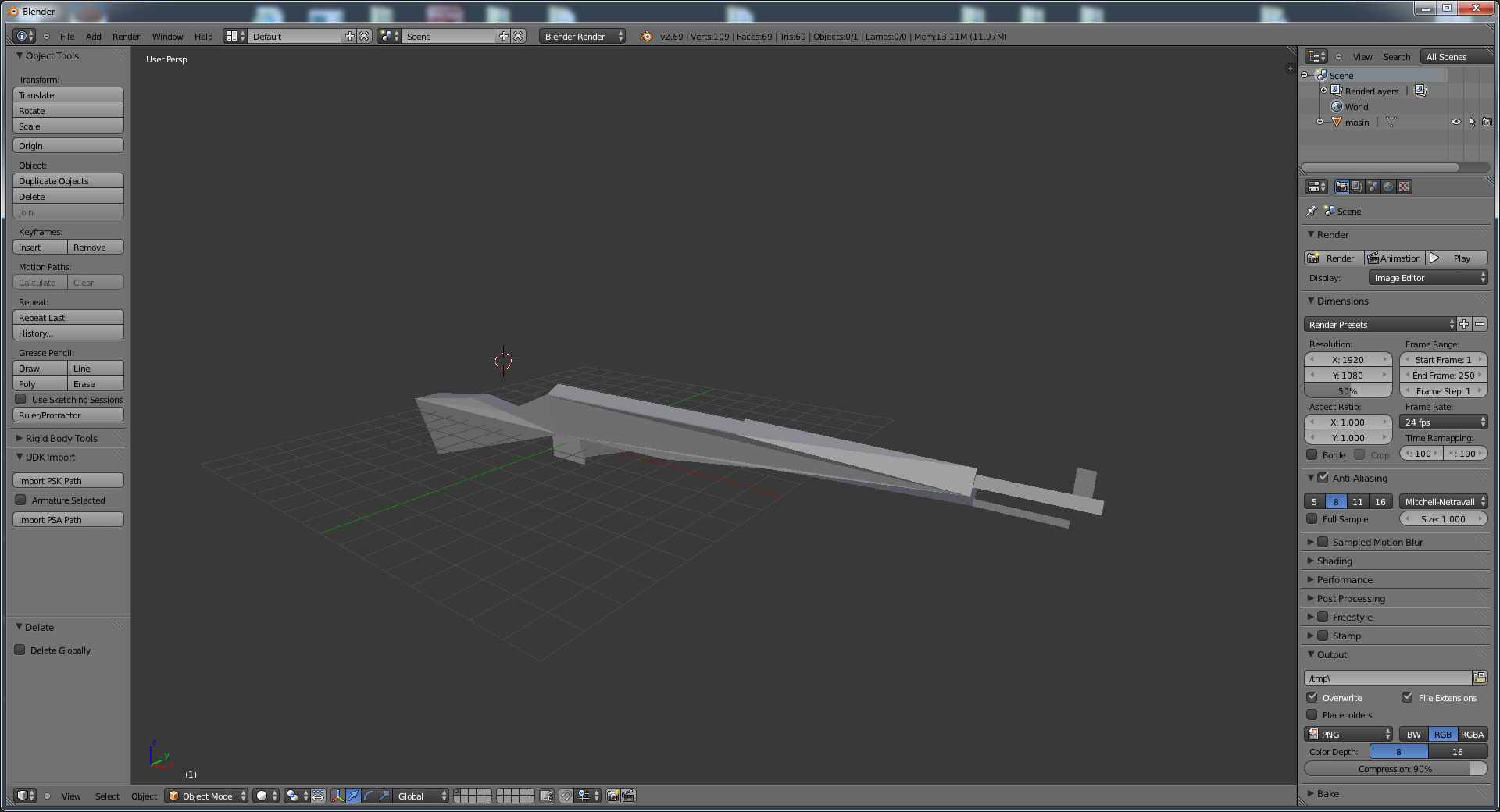
After importing the generated OBJ, this is what I see in Blender.
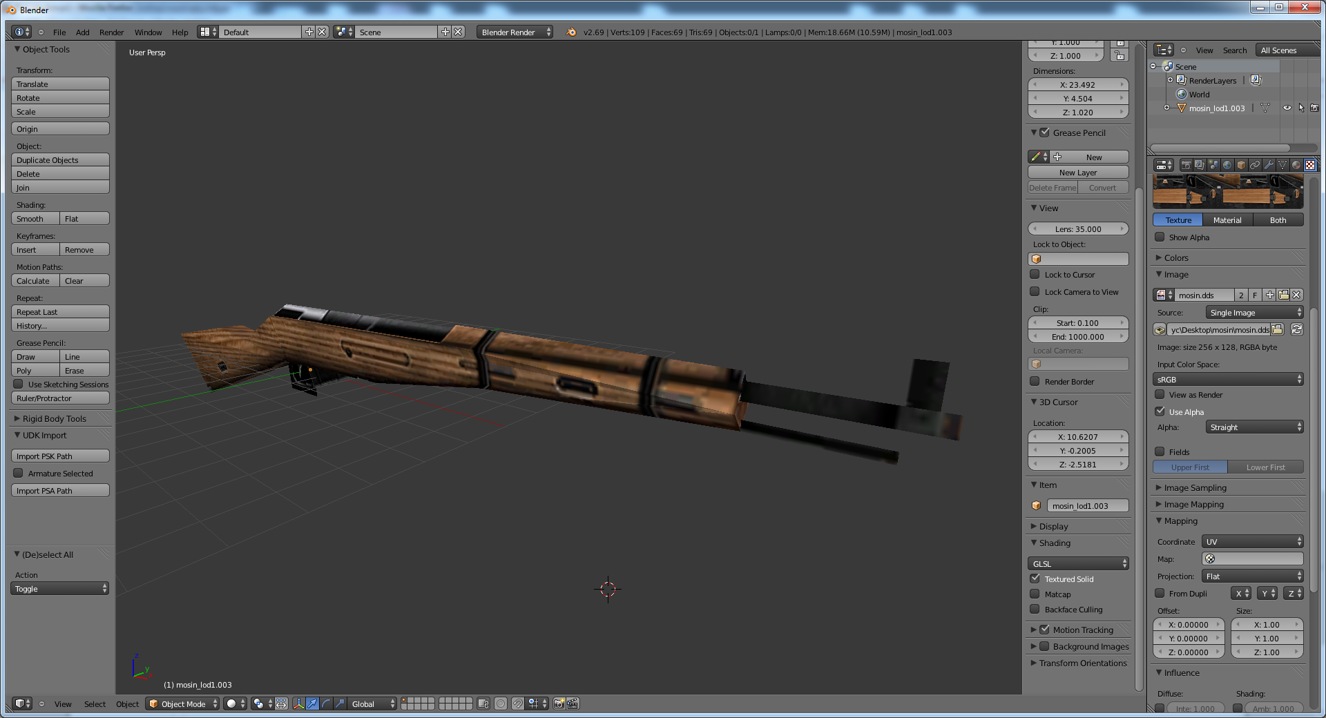
The next task is to find the UVs. The last eight byte in the vertex data look promising if converted to floats.
import struct

fname = "mosin_lod1.ply"
positions = []
indeces = []
UVs = []
with open(fname, "rb") as f:
    f.seek(0x2C)
    triangles, = struct.unpack("<I", f.read(4))
    print triangles
    f.seek(0x4A)
    verts, = struct.unpack("<I", f.read(4))
    print "Number of verts:", verts
    f.seek(0x52)
    for i in range(0, verts):
        vx,vy,vz,u1,u2,U,V = struct.unpack("fffff8xff", f.read(36))
        print "Vertex %i: " % i,vx,vy,vz
        positions.append((vx,vy,vz))
        UVs.append((U,V))
        #print "u1, u2", u1,u2

    f.seek(0xFAA)
    idx_count, = struct.unpack("<I", f.read(4))
    #print "Indeces:", indeces
    for i in range(0, idx_count/3):
        i0,i1,i2 = struct.unpack("<HHH", f.read(6))
        print "Face %i:" % i,i0,i1,i2
        indeces.append((i0,i1,i2))
    #print(hex(f.tell()))

fname = "mosin_lod1.obj"
with open(fname, "wb") as f:
    for p in positions:
        f.write('{:s} {:f} {:f} {:f}\n'.format("v", *p))
    for UV in UVs:
        u = UV[0]
        v = 1.0 - UV[1]
        f.write('{:s} {:f} {:f}\n'.format("vt", u, v))
    for idx in indeces:
        new_idx = map(lambda x: x+1, idx)
        f.write('{:s} {:d}/{:d} {:d}/{:d} {:d}/{:d}\n'.format("f", new_idx[0], new_idx[0], new_idx[1], new_idx[1], new_idx[2], new_idx[2]))
In the code, I subtract V from 1 to to flip the component to get the UV map to line up correctly with the image. Also, Blender and MoW use different ordering for back face culling, so I had to flip normals in Blender to have the model render correctly. This will be fixed later.
With vertex positions and UVs out of the way, the next task is to find the normals. Here is the breakdown of the first vertex: The red is vertex position (Vx, Vy, Vz), the pink is unknown, and the yellow is the UV.
struct Vertex {
float Vx, Vy, Vz;
uint32 u0,u1,u2,u3;
float U, V;
};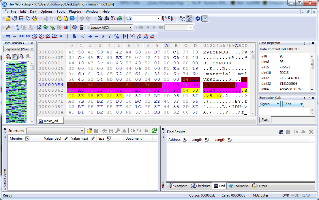
It is clear that the normal is 0x5DC30EBA = -5.4459815e-004, 0xB3AC583F = 0.84638518, and 0x915608BF = -0.5325709. To verify, I loaded the OBJ of the rifle in blender and printed out the vertex normals with the following script:
import bpy

v = bpy.context.object.data.vertices
for i in range(0, len(v)):
    print("Index",v[i].index, "Coordinate", v[i].co, "Normal", v[i].normal)
Here is part of the output:
Index 0 Coordinate Normal
Index 1 Coordinate Normal
Index 2 Coordinate Normal
Index 3 Coordinate Normal
Index 4 Coordinate Normal
Now, I modified the script to include the normals in the OBJ and fixed the vertex ordering:
import struct

fname = "mosin_lod1.ply"
indeces = []
positions = []
normals = []
UVs = []
with open(fname, "rb") as f:
    f.seek(0x2C)
    triangles, = struct.unpack("<I", f.read(4))
    print triangles
    f.seek(0x4A)
    verts, = struct.unpack("<I", f.read(4))
    print "Number of verts:", verts
    f.seek(0x52)
    for i in range(0, verts):
        vx,vy,vz,nx,ny,nz,U,V = struct.unpack("ffffff4xff", f.read(36))
        print "Vertex %i: " % i,vx,vy,vz
        positions.append((vx,vy,vz))
        normals.append((nx,ny,nz))
        UVs.append((U,V))

    f.seek(0xFAA)
    idx_count, = struct.unpack("<I", f.read(4))
    #print "Indeces:", indeces
    for i in range(0, idx_count/3):
        i0,i1,i2 = struct.unpack("<HHH", f.read(6))
        print "Face %i:" % i,i0,i1,i2
        indeces.append((i0,i1,i2))
    #print(hex(f.tell()))

fname = "mosin_lod1.obj"
with open(fname, "wb") as f:
    for p in positions:
        f.write('{:s} {:f} {:f} {:f}\n'.format("v", *p))
    for UV in UVs:
        u = UV[0]
        v = 1.0 - UV[1]
        f.write('{:s} {:f} {:f}\n'.format("vt", u, v))
    for n in normals:
        f.write('{:s} {:f} {:f} {:f}\n'.format("vn", *n))
    for idx in indeces:
        new_idx = map(lambda x: x+1, idx)
        # change vertex index order by swapping the first and last indeces
        f.write('{:s} {:d}/{:d}/{:d} {:d}/{:d}/{:d} {:d}/{:d}/{:d}\n'.format("f", new_idx[2], new_idx[2],
        new_idx[2], new_idx[1], new_idx[1], new_idx[1], new_idx[0], new_idx[0], new_idx[0]))
So, now the vertex looks like this:
struct Vertex {
    float Vx, Vy, Vz;
    float Nx, Ny, Nz;
    uint32 unknown;
    float U, V;
};
Reversing the Header
Comparing two different weapon files, it is clear that a pattern of the header structure emerges.

Part of the mesh entry is variable length:

Looking at a different model, the vertex header includes the vertex layout definition. This is highlighted in red and the yellow highlights one vertex entry.
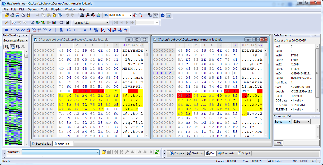
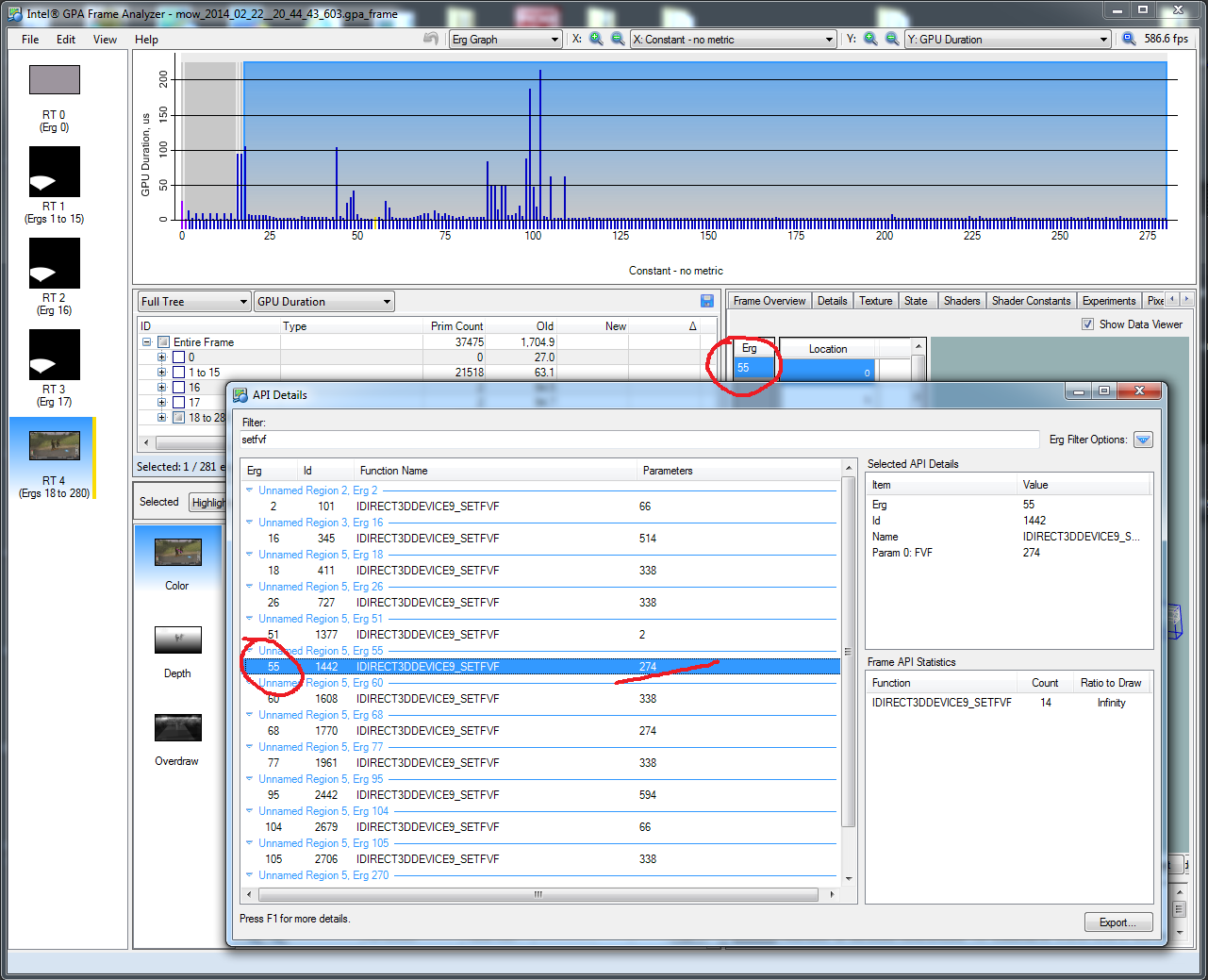
For the bazooka, the SetFVF parameter is 274 = 0x112. D3DFVF_XYZ 0x002 | D3DFVF_NORMAL 0x010 | D3DFVF_TEX1 0x100 = 0x112. It looks like the structure of the header is the following:
struct Header {
    char magick[8]; //EPLYBNDS
    float bounding_box[6];
    Mesh mesh;
};

struct Mesh {
    char magick[4]; //MESH
    uint32 unknown1;
    uint32 unknown2;
    uint32 faces;
    uint32 unknown3;
    uint32 unknown4;
    uint8 material_name_length;
    char material_name[];
    char unknown_data[]; // optional
    VertexData vdata;
};

struct VertexData {
    char magick[4]; //VERT
    uint32 vertices;
    uint32 unknown1;
    Vertex vert[];
}
There are several formats for a vertex:
struct Vertex {
    float x,y,z;
    float ny,ny,nz;
    uint8 r,g,b,a;
    float u,v;
};

struct Vertex {
    float x,y,z;
    float ny,ny,nz;float u,v;
};
Conclusion
The dumper script will be cleaned up and posted on github, but at least I can now dump most static meshed and look at them in a 3d editor. There are additional variations of the ply format for animated models, but those will be dealt with at a later date.
Notes
http://msdn.microsoft.com/en-us/library/windows/desktop/bb174433%28v=vs.85%29.aspx http://msdn.microsoft.com/en-us/library/windows/desktop/bb174464%28v=vs.85%29.aspx http://msdn.microsoft.com/en-us/library/windows/desktop/bb205866%28v=vs.85%29.aspx http://msdn.microsoft.com/en-us/library/windows/desktop/bb172559%28v=vs.85%29.aspx ttp://msdn.microsoft.com/en-us/library/windows/desktop/bb172558%28v=vs.85%29.aspx http://en.wikipedia.org/wiki/Wavefront_.obj_file